Very good photographic images can be made just with a box and a small hole serving as a lens. In this chapter we will deal with the size of holes and its optimum distance to the sensitive plate or film. Pinhole Camera for General work
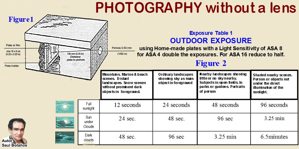
Film or plate can be square or rectangular and size can be varied, distance from pinhole to plate can be doubled or reduced to half without affecting definition too much. Diameter of hole can be from 0.25mm to 0.5mm. But distance given in figure1 is optimum for maximum sharpness, normal perspective and minimum exposure time with a 0.5mm diameter hole.
To use:
cover pinhole with black paper, load plate or film in the darkroom. Take camera out and place in a tripod or firm table, point the pinhole to the general direction of the subject. Uncover the pinhole to make the exposure. Do not move camera during this time. Cover the hole again with the black paper and take out film or plate out of the box in darkroom to develop it.
Focusing is not necessary because everything placed right in front of the camera to the far horizon will have the same focus. A 0.5 mm pinhole at 5.25 in. distance from the plate has a focal value of F 262. EXPOSURE TIME DEPENDS UPON THE SIZE OF THE PINHOLE AND ITS DISTANCE TO THE PLATE. For exposures using the camera above see exposure table 1 below.
Exposure Table 1
OUTDOOR EXPOSURE WITHOUT A LIGHT METER
using Home-made plates with a Light Sensitivity (ISO) of ASA 8 for ASA 4 double the exposures for ASA 16 reduce to half. See Figures 1 and 2 below.
Perspective is determined by hole to plate distance
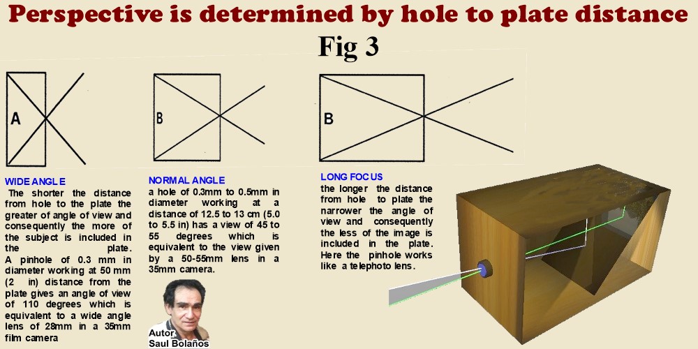
Fig 3 WIDE ANGLE The shorter the distance from hole to the plate the greater of angle of view and consequently the more of the subject is included in the plate. A pinhole of 0.3 mm in diameter working at 50 mm (2 in) distance from the plate gives an angle of view of 110 degrees which is equivalent to a wide angle lens of 28mm in a 35mm film camera.
NORMAL ANGLE a hole of 0.3mm to 0.5mm in diameter working at a distance of 12.5 to 13 cm (5.0 to 5.5 in) has a view of 45 to 55 degrees which is equivalent to the view given by a 50-55mm lens in a 35mm camera.
LONG FOCUS the longer the distance from hole to plate the narrower the angle of view and consequently the less of the image is included in the plate. Here the pinhole works like a telephoto lens.
The size of the image
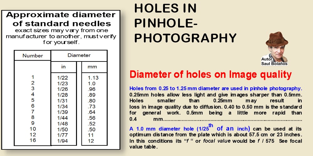
depends upon the subject’s closeness to the camera and its quality and definition upon the size and sharpness of the hole. Within certain limits a pinhole has no plane of focus as proved by the fact as practically the same results are obtained by having the sensitive plate at different distances from the hole. There is an optimum (but by no means critical) size of hole for any particular hole to plate distance. For the best possible results the pinhole must be circular with perfectly clean edges without the slightest blur.
Quick 0.50 mm pinhole
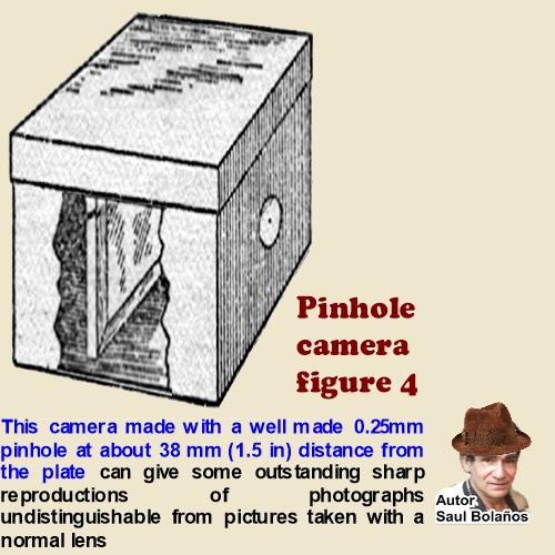 A number 10 needle will perforate a piece of black paper with a hole of about 0.50 mm (1/50th of an inch) diameter. Although never as good as a properly done hole on metal, it can be used in front of a box to make amazing pictures. Figure 4 Pinhole Camera for Copying and photographing small objects on scale of 1:1 (Macro Work)

Theoretically
Optimum Plate to Hole Distances
holes 0.25 to 1.25 mm diameter can be used anywhere from 1.5 to 30 inches from the plate
with good results but the theoretically best distances according to hole sizes are as follows in inches
and rounded off in millimeters. It will be seen that a 0.5 mm hole should be
around 5 inches or 125 mm from the plate.
For Macro work
a 0.25mm hole at 35-38 mm distance from plate is perfect.
HOLE SIZE PLATE DISTANCE
inches mm inches mm
1/50 0.5 5 125
1/75 0.33 2.5 62
Advantages of Pinhole Photography
1.There is no Distortion, lines in architecture are strait.
2. Depth of field extends from the camera to the horizon
3.Absolute freedom to vary the perspective of the subject and scale of reproduction by altering the relative distances of the plate and the subject from the pinhole.
Disadvantages
1.“f” or focal value is altered with every change in distance of plate to hole.
2 . Long exposures
3 . No moving objects possible.

-----------------------------------------------------------------------------------------------
Blackening the pinhole refer to Figure 6
 see in figure below where I use the opposite end of an ordinary drill to make the indentation on the metal. The piece of metal to be indented is placed against a hard metal surface,
the point of the drill carefully placed on top on the point where the hole is going to be made and force is applied with a hammer. Usually I make the indentation in about 3 to 4 hammer blows each blow increasing in force and exactly in the same point. When the indentation is seen to be deep enough and it has been ascertained that the whole of the depth of the metal was not perforated trough by examining it against the light; the next steps are performed see below
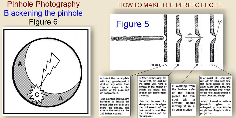
for maximum image quality the edges of the pinhole must be blacken as in AA this will avoid diffusion of the captured image by light reflections shown at "C". Refer to Figure "5"
HOW TO MAKE THE PERFECT HOLE
Without the that technique it is exceedingly difficult to make a clean perfect hole. The best is to perform the hole on a metal plate which can be brass, aluminum, stainless steel or any other thin metal. A thickness from 0.25 to 1.0 mm is fine. I prefer no thicker than 0.75mm and a soft metal like brass, copper, aluminum. But even tin or galvanized sheet iron or any other metal can be used.
The technique consists first in making an indentation on the metal but not perforating it.
The point where the metal is indented is made thinner than the rest of the metal surrounding it and it is here in this thin part where the metal is perforated. Second: After indentation, the perforation is done with a sewing needle of required size as shown in figure. above.
BLACKENING METAL
Immersion in thiosulphate or the hypo bath used as the normal photographic fixer can be used for blackening many metals. Alternatively the metal can be placed in contact with a disk or heating element of a domestic oven and heated until red. When cooled by immersion in cold water many metals will retain the black color. Another way is to spray paint it very lightly with an aerosol matt black paint shaking the black paint can vigorously before every pass. The hole, after any of these treatments, should be inspected as to its cleanness and sharpness.

Figure 8
In Figure A, "A" is an acrylic transparent ruler which is placed in negative carrier of photo enlarger B. The ruler’s markings are thus enlarged by projection as seen in C onto a sheet of paper D. The magnified image of the ruler, lets say 1 millimeter, greatly enlarged is then traced by hand on the paper shown as D.
After tracing the desired ruler’s marking, without disturbing the set magnification, the ruler is taken out of the negative carrier; (refer now to figure B) and in its place the pinhole is now inserted in the negative carrier to be enlarged onto the scale previously traced on the sheet of paper D. The enlarged projected image of the pinhole is shown as F in figure B where the pinhole according to scale shown is a little less than 0.5 mm in diameter.
the needle is again re inserted working on both sides of the hole until sharp, clean and perfectly clear instead of a photo enlarger a slide projector can be used.....
 Focal Values
Focal Values of Pinholes
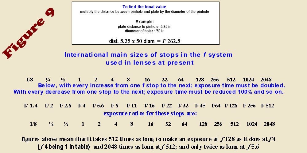
In the table of figure 10 the ratio aperture
("stop value") is given for a certain extension of the camera;
if any other extension is used the ratio aperture must be found by multiplying the distance
between pinhole and plate by the diameter of the pinhole.
The Formula is shown in fig 9 as follows:
MOUNTING
THE PINHOLE AND SHUTTER
Photography with out a lens with a 35mm camera
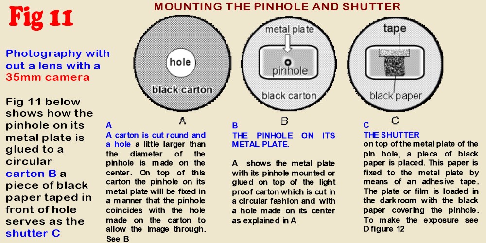
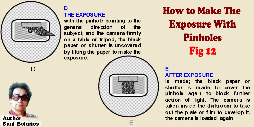
Fig 11 ABOVE shows how the pinhole on its metal plate is glued to a circular carton B a piece of black paper taped in front of hole serves as the shutter C, how to make he exposure with pinhole camera is shown in figure 12 "D" and "E" below.
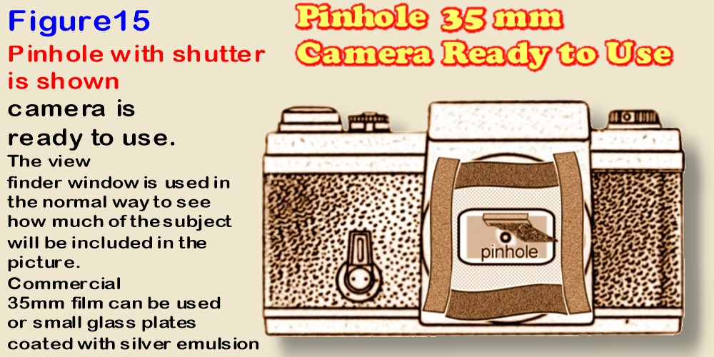
Mounting the pinhole
IN ANY 35MM CAMERA FOR PINHOLE PHOTOGRAPHY
In figures below, pinhole can be of any diameter between 0.25 to 0.60 mm. The distance from film plane on to back of lens on these cameras is always between: 35 to 40 mm, we figured out the focal value of such pinhole mounted such arrangement on Figures below 13 and 14.

Refer to Fig 12 Pinhole mounted on its carton as described earlier, is placed right in the center of in front of film plane after taking normal lens out of the camera. Distance from film plane to pinhole or normal lens is usually between 35 - 39 mm. In Fig 13 Pinhole is simply fixed to the front of the camera by means of black vinyl electrical tape which will block any light from entering through the sides of the carton.
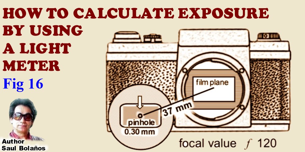
HOW TO CALCULATE
EXPOSURE BY USING A LIGHT METER
SEE Figure 16 BELOW
One of my pinhole cameras shown above, has a pinhole of 0.30 mm diameter at a distance of 37 mm from the plate To find the focal or f value, (which for all practical purposes means the aperture) of this arrangement I proceeded in this way:
A first translate all millimeter to inches thus:
0.30mm= 1/81 inches ( 25mm divided by 81= 0.30mm)
we have now the diameter of pinhole in inches, next translate the 37mm distance to the plate to inches:
37mm divided by 25mm= 1.48 inches.
To get the focal value now we use the formula given earlier, thus
1.48in distance X 1/81 pinhole diameter = f 119.88 which rounds off to f 120.
Now I know F 120 is my working aperture to estimate exposure.
B next I compute the square area of f 120 simply thus: f 120 X f120 = F 14.400
now using any light meter I take a light reading of the scene to be photographed and choose a speed and an aperture from the readings given by light meter.
Example: the light reading taken with the meter gives the following exposure options: f 2.8 at 1/30th which is equivalent to: f 4 at 1/15th or 1/8 at f 5.6 and so on. Let’s say I choose as an aperture f 2.8 at 1/30th second from the many equivalent exposures given by the light reading.
C next I find the square area of the chosen aperture by multiplying it by itself f 2.8 X f 2.8 = F 7.84
D How many times does f 7.84 fits into f 14.400? The answer:
dividing F 14.400 by F 7.84 = F 1836
the exposure time given by the light meter has now to be multiplied by 1836 In other words f 120 allows 1836 times less light than f 2.8 all and any exposure time given by the light meter will have to be multiplied by 1836 times which becomes the exposure factor of this camera fitted with that size pinhole at that distance (as long as f 2.8 is always chosen as the aperture on which the light reading is based) Now we had chosen 1/30th of second at f 2.8 as the exposure.
E. translate 1/30th to decimals thus: 1 divided by 30 = 0.033 the exposure required with this pinhole will be: 0.033 sec X 1836 = 61 seconds,
Assuming I move some where else and the brightness of the scene calls for example 1/125th at f 2.8 I divide 1 by 125=0.008 which X 1836 = 14.688 seconds or about a quarter of a minute would be the exact required exposure using that pinhole. Now I take another picture under a very poor lightening where the light meter reads: 1/4 sec at f 2.8 in decimals 1/4 would be: 1 divided by 4 = 0.25 x 1836 (my pinhole factor for f 2.8) = 459 seconds will be the exact exposure now.
if another f stop other than f 2.8 is chosen to base the light meter reading on then as explained in C. above; - find the square area of the chosen aperture by dividing it by itself. Example: light meter reading calls for: 1/125 of a second at f 8, then multiply: f 8 x f 8 = f 64 now do the math...
again dividing the square area of f 120 which is F 14.400 by F 64 = 225
the exposure time given by the light meter has now to be multiplied by 225 times. 225 will be a constant exposure factor as long as the aperture chosen in the light meter reading remains always f 8. Now since we had chosen an exposure of 1/125 at f 8 for this example, it remains now to translate the 1/125 of a second into decimal fractions as described earlier thus: 1 divided by 125= 0.008 0.008 X 225 = 1.8
1. 8 seconds will be the exact exposure.
Of course it can be rounded off to 2 seconds. In practice if one uses always the exposure reading given by the light meter pointing to always the same aperture, the math is very quick and simplified because it takes only the translation of the shutter speed to decimal fractions and multiplying this result times the exposure factor to get at the exposure time.
This method is perfect though it takes a lot more time to describe than to practice it. It yields excellent negatives every time without the uncertainty of guessing exposures. Coating glass plates with one’s own emulsion takes time and effort and no need to waste then by exposure errors.
PHOTOGRAPHY WITH OUT A LENS
AND COATING YOUR OWN PLATES
Fig 17 Nothing more satisfying for an artist than to use universal principles that do not change such as photography with just a small hole. On top of that the experience can still be more fulfilling if the workers prepare the sensitive plates himself. The preparation of Gelatine Silver Bromide Emulsions are fully dealt somewhere else in this book.
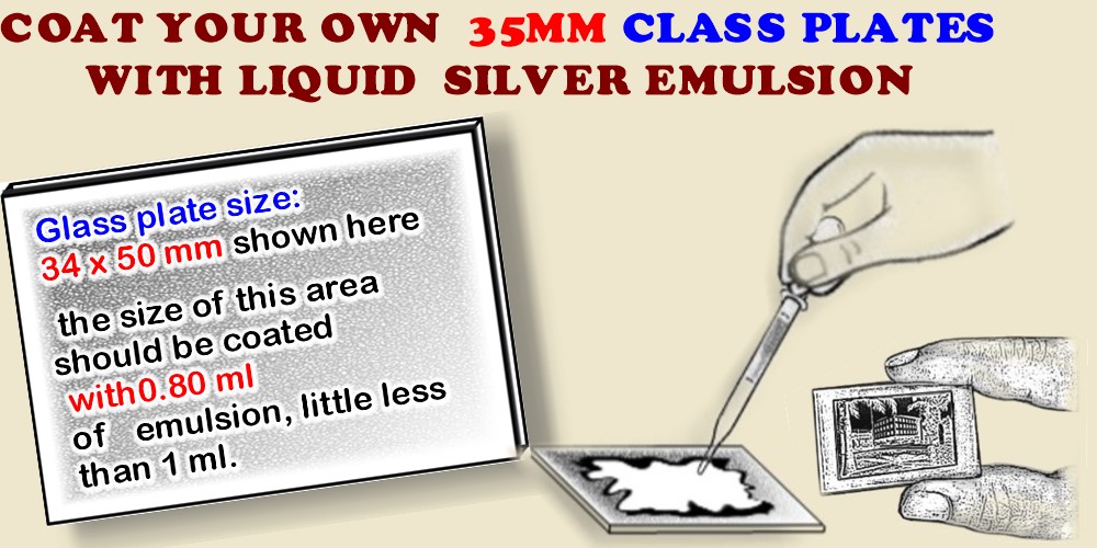
Figure above shows a small ordinary window glass plate which after being coated with emulsion and dried is placed on the focal plane of any 35mm single lens reflex camera to take pictures either with a pinhole or its normal lens. Instead a 35mm camera any twin lens or range finder camera can be used. The thinnest window glass should be procured (about 2mm thick,-if thinner the better.
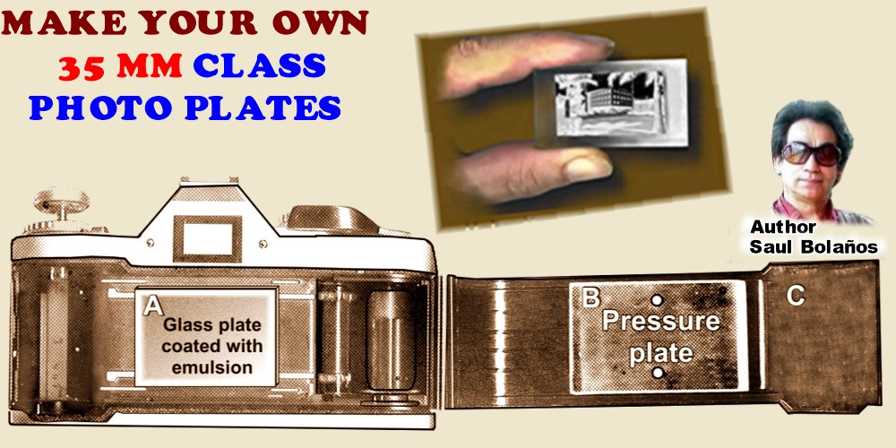 REFER TO FIGURE ABOVE: "A" is a 50 x 34 mm ordinary window glass plate made sensitive with silver emulsion which is placed on top of the focal plane of the 35mm camera for making the exposure. As long as the glass size is not wider than 50mm, (there is no reason why it should be) the pressure plate shown as "B" will not interfere when the camera’s door "C" is closed.
I have 4 types of 35mm cameras that can be used without having to remove the pressure plate "B" which by the way can be dismounted on most 35mm reflex cameras. On one of my cameras the pressure plate was dismounted permanently because I use it very often at the My Research Labs to test negative emulsions on glass.
Glass plate should not be higher than 34mm because cameras door "C" shown in picture above may not close, but it is easy to dismount pressure plate "B", in most SLR cameras, that way thicker glass plates shown as "A" can be used behind the lens.

CONTACT

COSTA RICA © 2025, saul bolaños
CAFEDESAUL@GMAIL.COM